This is a part 1 out of 3. PCBs were sponsored by PCBWay.
A long time ago I decided upon passive 48 V PoE for my network. Choice was made due to both hAP ac and Audience access points supporting up to 57 V. Thus 48 V was closest lower standard value with a reasonably priced power supplies. However, this decision came to bite me in the ass with my new hAP ax³ supports going only up to 28 V. Placing it into my network would lead to a lot of sparking fun. What I needed was a lower voltage.
Well, the next logical step was switching to 24 V. However, buying two 24 V power supplies (one to use, and one for backup) allowing for 60 W was actually not that cheap. Since I had bunch of leftover power supplies, I started to wonder if I could use something I already have.
Yes, I could have used one of vendor-specific laptop power supplies but that would involve cutting cables as their connectors were anything but standard. The only standard connector I had was type-C. And then it hit me. Why not simply use power delivery to get 20 V out of it?
Realistically, probably the easiest in-place replacement was one of many prebuilt cables out there. And I think this is the best way to go if you just need power. But, for my home setup I connected PoE over ResetBox device which allows for an easy power reset. Wouldn't it be really nice if I updated ResetBox to directly use type-C?
And no, ResetBox is not just a simple switch albeit it offers essential functionality of one. Its a bit smarter than that as it contains microcontroller that gets to control a relay. For example, it will ignore short, accidental, presses and allow reset only when held for 3 seconds. Ideal for controlling things you don't want to reset by accident - for example your home wireless network.
For this update it would be ideal to switch input to type-C, allow for on-board voltage selection (5 V, 9 V, 12 V, 15 V, and 20 V), and lastly have a nice way to indicate the selected voltage.
With that in mind, the first task became selection of PD chip. It is possible to control PD on your own but I quickly decided against it as setting it to function right with various PD and non-PD type-C devices would take ages. No, I wanted something standard.
Quick search quickly pointed toward IP2721 as a reasonably easy to (hand)solder device used in many existing triggers. However, its package was a bit on a large side and voltage output was quite limited since it only supported 5 V, 15 V, and 20 V operation. Definitely not a full set of voltages I wanted. And yes, you could get lower voltages by using IP2721_MAX12 variant but then you lose the higher voltage options.
Second device I found was HUSB238 and I immediately liked its SOT33-6L variant. Unfortunately, this easy-to-solder variant was nowhere to be found for purchase. Even worse, the chip didn't support the full PD 3.0 5A operation. Yes, probably not a deal-breaker for this particular scenario as 60 W was plenty but still no ideal for a new design.
After quite a lot of additional search I stumbled across CH224K. Not only it came in (seemingly) easy to solder ESSOP-10 package but it also supported easy control. Based on a few examples I found it seemed possible to tease the full 100 W with it.
The datasheet also mentions an even more appealing CH221K in the SOT23-6L package, but I had difficulty finding it in the market. On the other hand, the ESSOP-10 variant was readily available all over AliExpress.
With chip selected, the second order of business became figuring out how to connect all this. With only 6 I/O pins available, the current PIC12F1501 was a bit crowded. In addition to 1 button input, 1 LED output, and a 1 relay output it already handled, I would add 3 outputs for voltage control (also used to show LEDs status). Total of 1 input and 5 outputs. Not comfortable but just enough.
Originally, ResetBox had the option to handle AC input. However, with type-C, this is no longer necessary, so we can replace the relay with a small P-MOSFET and completely bypass the diode bridge. We don't control this MOSFET directly, but rather via a small NPN transistor. This approach serves two purposes: first, it prevents our PIC from seeing 20 V at any given time, and second, it allows the PG signal to override the output (i.e., no PG, no voltage).
While originally ResetBox had option to hadnle AC input, with type-C we don't need this anymore and thus we can replace relay with a small P-MOSFET and omit diode bridge altogether. We don't control this MOSFET directly but over a small NPN transistor and that's for two reasons. First one is to avoid our PIC seeing 20V at any point in time and the second reason is allowing PG signal to override output (i.e. no PG, no voltage).
The power supply for the main PIC is managed by an LDO. While this approach does waste some energy, it's not too significant as the PIC won't need more than roughly 20 mA. For such a small current, it simply wasn't worth opting for a switched-mode regulation. I considered using a 5 V LDO despite the input being at 5 V, but chose to make the smarter decision and go with 3.3 V instead. And yes, I did test the 5 V LDO in the same circuit and it worked, albeit with a slight voltage drop.
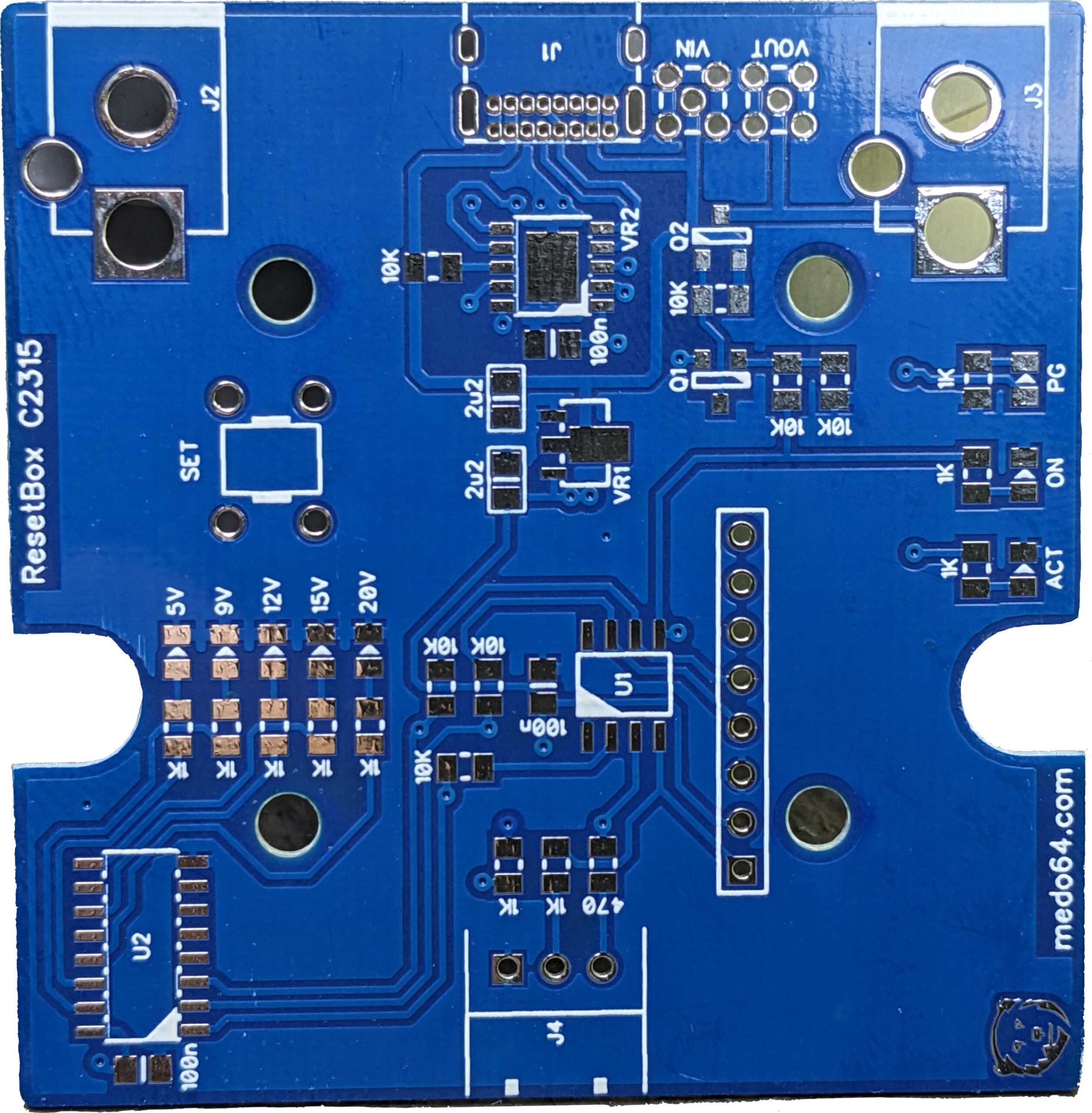 For PCB creation I chose PCBWay and they generously provided me with free PCBs. As it's common with my projects, I don't really push the boundary of what's possible but there were a few non-standard things with this PCB. The first one was its thickness as I needed
 0.8 mm due to type-C connector. The second one were really small holes for the same. And yes, this was quite well within the specification but I actually had issues with this when it came to other PCB manufacturers.
But more about that the next time when I go over all the things I've botched during the PCB design.
Latest design is available on GitHub