 Powering device via USB has its advantages even if device doesn't need connectivity. Most notable of those advantages is a wide availability of USB battery packs. That makes powering device really easy. However, what if your device uses so little power that batter pack keeps turning off?
All three battery packs I had available had the same issue. Put something that pulls just a trickle of current and they would turn off. One of them did have a trickle-charge functionality and that sorta worked but required manual intervention. And yes, I forgot to turn it on more times than I care to remember.
So I went looking for solution and found Dorkbot PDX article by Paul. The way how he solved this issue was quite a nice one. Just put intermediate load on the bus and you're golden. Instead of going with his solution, I decided to use my favorite hammer - Microchip PIC microcontroller - to make my own board using the same concept.
Realistically, there's no reason to use microcontroller for this. Having a programmable part just introduces assembly complexity and you cannot use it out of box, without programming it first. But there are advantages too. The major one being adjustability and that came in really handy when figuring out the timings needed. Instead of dealing with large value capacitances, one can use inherit time keeping mechanisms of microcontrollers. Furthermore, it also allowed for easy placing of blinky light. And who doesn't love those?
The whole solution is based on a small 6-pin PIC10F200 microcontroller. When you discount programming pins, that leaves you one pin to work with. And yes, you can pretty much use programming pins too (3 of them) if you use a few extra passives but I generally leave them alone if I can. Fortunately, application I had in mind was simple enough to solve with a single pin.
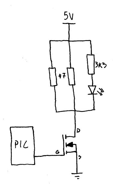 The device logic is as simple as it gets. To keep the battery pack turned on, it uses MOSFET to pull 200 mA over two resistors for about 20 milliseconds. Once pulse is sent, wait for 10 seconds. Rinse-repeat. On all packs I've tried this combination worked flawlessly. Of course, if there's a pack where this doesn't work, adjustment is easy enough (yes, I will update code with some constants later :)).
The heavy lifting is done by MOSFET driven directly by microcontroller. Once turned on, it will allow two resistors to dissipate a bit over 200 mA of current. While this seems like a significant amount of power to pass over puny 0805 resistors, short duration means they will never get hot enough to present a problem.
One could also take an offense to how MOSFET is driven too. Due to the nature of the beast a lot of current will flow out of the gate pin and by common knowledge one has to have a resistor to limit it. However, this MOSFET is small enough that current limiters built-in to Microchip PIC microcontrollers are fine. I had even bigger MOSFETs work in circuit for years without gate resistor so I am not too worried. That said, if I ever change to different microcontroller, some reevaluation will be needed.
And yes, there is no bleed-off resistor on MOSFET gate either. If circuit is powered on, PIC will be driving it either low or high so pulling the MOSFET gate down is not really needed. If circuit is not powered on, who cares - there's no power to go around anyhow. That leaves only the short amount of time when circuit is powered on and PIC is not yet driving the gate. And that is the interval we can safely ignore as it's shorter than 20 milliseconds and even erroneously active MOSFET will cause no damage to the circuit in that time.
Thanks to Microchip's semi-standard pinout, this device can use any number of PIC microcontrollers. As long as footprint fits (SOT23-6), you're golden. I have tried it with already mentioned PIC10F200 and PIC10F320 but any variant should work too. Yes, the firmware did need a bit of adjusting between methuselah PIC10F200 and newish PIC10F320 but those were simple enough. In these times of chip shortages, having multiple parts fit is always a nice thing.
 How much battery this uses, you might ask. It would be a bit annoying to have your battery drained by a device whose only purpose is to keep it awake. Well, to start with, we need to account for all power usage. The main one is of course our 220 mA pulse (
5V/(47Ω÷2)) lasting 20 milliseconds. Since it repeats every 10 seconds, that leads us to a duty cycle of 0.2%. Multiply one by another and we can see that average power usage is about 0.5 mA.
Second power user is our LED that blinks with the pulse. Due to large value resistor, it will require slightly less than 1 mA for each pulse. Using our duty cycle, that us average consumption of 2 µA (0.002 mA). Pretty much a noise compared with our load.
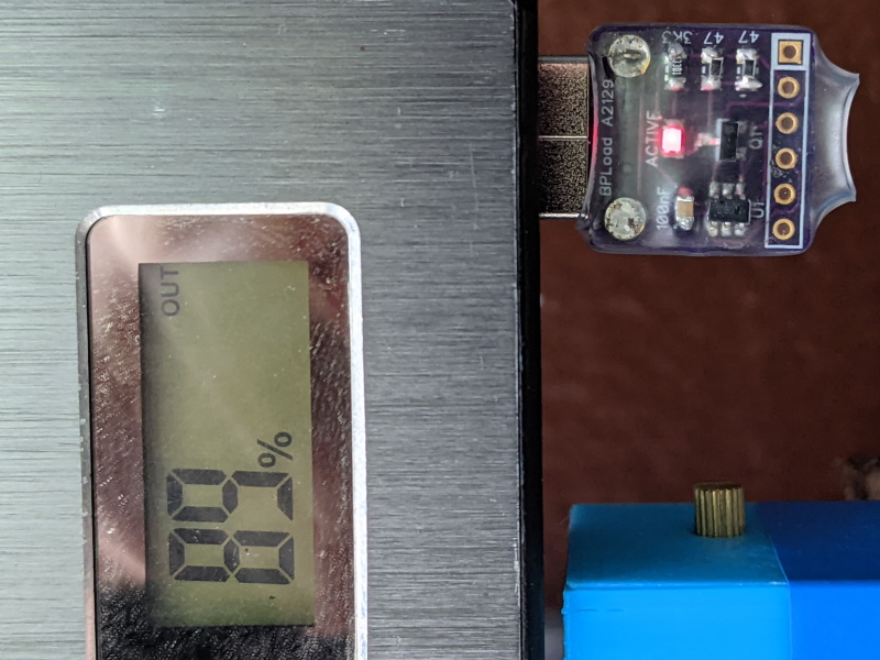
And lastly there's the PIC itself. Good news is that this is well under 1 mA. How much under? I have no idea as I didn't have anything capable of measuring it. I will definitely need to create a board for that too. However, I did use USB power meter to get a long term reading of the usage and it was slightly under 0.5 mA (averaged over an hour) if using PIC10F320. For older PIC10F200 usage is a smidgen above it.
Those reading more carefully might wonder, if a power pulse needs about 0.5 mA, and total consumption is under 0.5 mA, we have the free energy as microcontroller is actually using the negative power from a far dimension to run itself. Sadly, it's not so. Due to how MOSFET is driven, it won't turn on nor it will turn off instantly. So our 200 mA pulse average will actually be lower. And PIC consumption is low enough to "hide" in those numbers.
Code actually runs constantly in the background due to a quirk of PIC10F200. If you put it in sleep, it resets itself (by design) making it annoying to keep track of time longer than 2.3 seconds. I was toying with idea of just using the newer PIC10F320 but power usage of constantly running PIC was low enough that I decided not to care.
Either way, if you have 10000 mAh battery, this device could theoretically run for 20000 hours. Suffice it to say that it shouldn't reduce battery life too much. If you really want to squeeze the last possible mAh out of it, you could adjust timings. For example, my Anker power bank was quite happy with more than a minute between pulses (0.033% duty cycle). However the default 0.2% duty cycle is probably a good starting point when it comes to compatibility.
Lastly, there are actually two versions of the device. The "normal" one just plugs in USB port while pass-through has a female USB connector on it allowing it to be used on battery packs with a single type A output. You can find gerbers for both on GitHub alongside with the source files.