 It all started with an itch to scratch. My modem occasionally misbehaves and needs a reboot. Unfortunately, I have it mounted way back in the 19" rack and accessing it requires removing back panel. And no, I cannot easily unplug it's connected to UPS and wires are all tucked in the back. What I needed was a button in one of rack spacers allowing for reboot of equipment in the back.
Since I couldn't find something like this readily available, I decided to build it.
First I enumerated all the equipment I have. One modem (12 V), one NUC (19 V), and finally two wireless access points (48 V). I was at crossroads. As voltage range is quite wide I had to choose if I want to make device work of specific voltage (cheaper) or to have a single device covering all the bases (more expensive). While going cheaper was tempting, I decided to go with wide input after all. It meant I can design thing only once and use it later for some other project without having to check voltage rating each time.
This decision also made me select DC-DC converter module. Making my own wide range converter would be possible but getting it just right would take annoyingly long time and actual cost wouldn't be much lower. Yes, at $5 R-78HE5.0-0.3 is not cheap but it's simplicity is worth every penny. If I ever decided to produce this box in bigger quantities, this would probably be the first thing to go in order to lower expenses and simplify design.
While not necessarily mandatory, I also opted to include EMC filter for DC-DC converter. Considering low currents it's probably an overkill but I really didn't want to find out later that I'm spraying too much noise around my rack. Design improvement would be to either remove filter all together (probably possible due to low current requirements) or make it much simpler and hopefully omitting SMD inductor. I hate to solder that stuff.
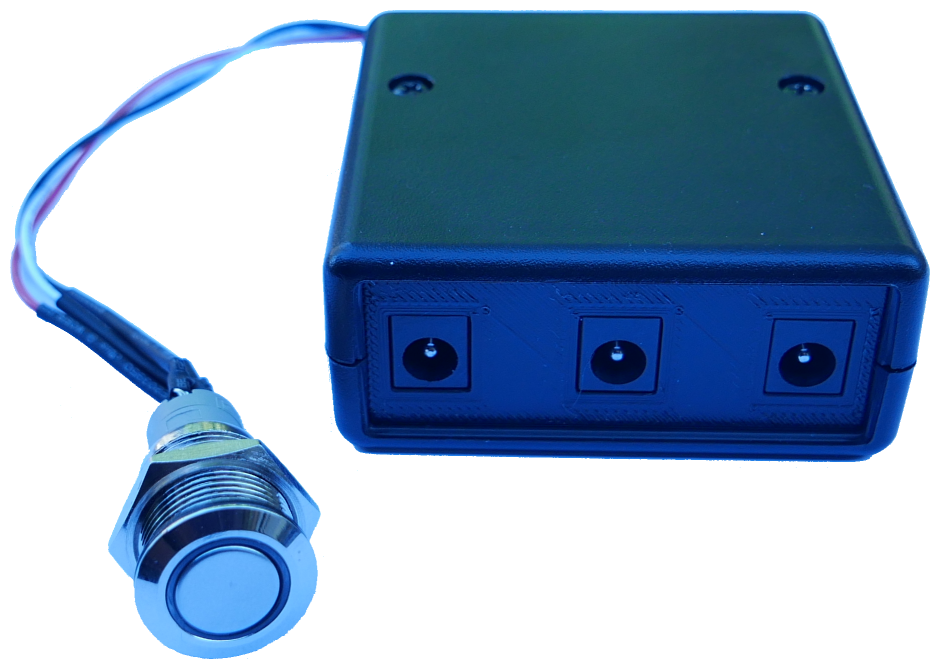
It took me a while to find a button as I wanted momentary switch with LED (excellent for giving status) and it had to look nice in rack. I finally found Adafruit's S 560. This button is awesome in person.
To connect button, I selected JST S3B-XH. I needed the minimum of three wires (GND, LED, and switch input) and I already had bunch of premade cables made in the course of another project. If I had only this project to worry about, I would probably select 4-wire connector as it would make soldering a bit easier. Not it's too hard now - just wire GND to both LED and NC input and you're golden.
Voltage connector choice was extremely easy as literally all devices I wanted to control already used barrel connector. Since 2.1 mm barrel had became a defacto standard for network cameras, this also meant I could count on connecting it all with factory cables making the whole setup a bit nicer.
Speaking of which, I mulled long time about whether I should support only barrel setup with positive voltage on tip and negative voltage on sleeve or the inverse one too. All network devices I ever owned have positive tip. However, I decided to allow negative tip setup to. I am 95% sure this was completely unnecessary precaution but at least I don't need to worry about it.
As far as saving money goes, supporting only positive tip barrel connectors, would allow me to remove diode bridge on input and allow me to replace mechanical relay with MOSTFET. As I'm making only 3 devices, for now I value flexibility the most. But decision to include these still bothers me a bit.
Housing hardware fell to Hammond 1593KBK. This is a reasonably sized and more important reasonably priced case with side panels. While I usually replace such panels with custom PCB with cutouts in place of connectors, this time I opted for 3D printed version. It's definitely cheaper than PCB but it does require you to have printer. And no, it's not as nice as PCB panel but it looks good enough - especially since device will sit in the back of the rack.
Lastly, I had to select microprocessor that would handle all logic. As most of my devices, I simply went with selecting Microchip's part. I needed two outputs (LED and relay) and a single input (switch). In order to avoid complications, I like to keep programming lines separate too (MCLR, PGD, and PGC). Yes, you can share these lines with logic if you're careful but having them reserved is one way to make sure. Once you include power supply, there is variety of 8-pin microcontrollers to chose from.
Finally I went with PIC12F1501-I/SN. It has 8 pins which is what we needed. SOIC package makes it easy to solder and internal oscillator minimizes extra components needed.
Code running on chip is as easy as it gets. What follows is the main loop.
void main(void) {
    io_led_on();
    while(true) {
        if (io_switch()) {
            if (debounceCounter < DEBOUNCE_MAX) {
                debounceCounter++;
            } else {
                intensityCounter++;
                if ((intensityCounter % 8) == 0) { io_led_on(); } else { io_led_off(); }
            }
        } else {
            if (debounceCounter == DEBOUNCE_MAX) {
                io_relay_on();
                for (int i = 0; i < RESET_COUNTER; i++) {
                    io_led_on(); wait_short();
                    io_led_off(); wait_short();
                }
                io_relay_off();
            }
            io_led_on()
            debounceCounter = 0;
        }
    }
}
If button is pressed, counter (debounceCounter variable) gets increased while button is pressed and until it reaches maximum. Side effect of handling counter like this is automatic debouncing and making sure short, accidental, swipes don't activate reboot functionality. Once at maximum, counter stops and we dim the LED so user knows reboot will follow once button is depressed. Dimming is actually done by poor man's PWM - just turn LED manually on 1/8 of interval (when counter is divisible by 8).
Second path executes only when the button is not pressed. If debounce counter is at maximum, a simple reset sequence starts. Here we disconnect relay (ironically by turning it on as it's normally-connected setup) and LED blinks for 4 seconds. Then we turn relay back off so that power returns to the device.
It's probably the simplest code I've written in quite a while.
If you want to check it a bit more, feel free to look up both board and code at GitHub.