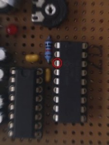
 Electronics is hobby of mine. Whenever I feel like relaxing I get myself PIC, some additional hardware and I make a board. This time I wanted to make LCD driver. Not for full-blown graphic LCDs but for small character ones. Yes, I know that there are solutions freely available for that exact purpose but reinventing a wheel is probably most important aspect of a hobby engineering.
As soon as powered whole mess of parts - nothing happened. Fault was easy to locate - it must be in my PIC code. After spending hours simulating in MPLAB (where everything seemed alright) I decided that board must be at fault. Quick test with LED lights showed that my LCD clock line (E) was dead. It took changing PIC chip and half of hardware before I acknowledged defeat and went down standard road - When everything else failes, RTFM.
As soon as I started looking into datasheet I had one of those enlightenment moments and I recalled similar problem I had on one previous board. RA4 pin (and only RA4) I was using is open-drain input on that particular chip. In practical sense it just means that pull-up resistor is needed for it to be of any use as output.
One cent component was all that was needed for LCD to be alive.
This whole experience was quite humbling since I was dealing with PIC I already knew and I thought that re-reading manual was waste of time. Of course Murphy found a way to teach me a lesson.