 [This post is part four in the series.]
The most difficult part of board setup is done for us - we have both dimensions and we've decided on components. Even better we don't need to think about board much as our HAT specification has it all sorted out. Or does it?
If you make board based on HAT specification you won't be able to fit official case around it. We need additional cutouts if we want it to fit - bigger on the left side and just a small one on the right. As board is not really crowded, it was easy to carve out the additional space. However, it might not be as easy for more dense layouts.
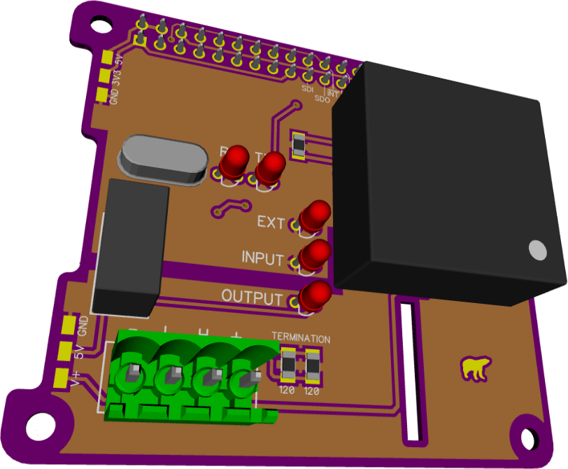 Top side is dominated by our DC-to-DC converter and nice 3.81 mm 4-pin CAN bus connector. Additionally there are through-hole LEDs so we can see activity and a through-hole oscillator purely because I hate SMD ones. To help with troubleshooting a few pads without solder mask are along the edge.
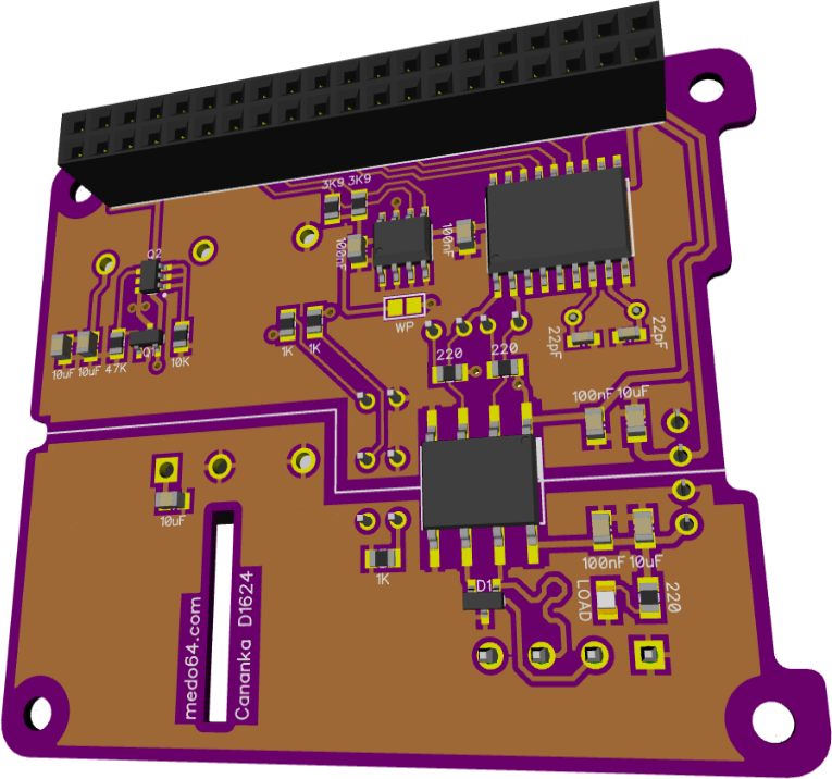
The whole board is essentially split into two parts. On top we can find components that can safely connect to Raspberry Pi. Most notable being MCP2515 CAN bus controller and 24C32 EEPROM needed for HAT compatibility.
Between CAN bus connector and controller we have isolation border crossed only by isolated DC-to-DC converters and ISO1050 CAN bus transceiver. Two millimeter spacing between these two universes should provide adequate protection.
It is a pretty straightforward layout mostly driven by the need to have isolation border and the size of the components.